
Universal Asynchronous Receiver-Transmitter (UART)
This experiment introduces serial communication using the TM4C123’s UART modules. You will configure UART0 for 115200 baud operation on pins PA0 (RX) and PA1 (TX), implement character and string transmission functions, and create an echo server that receives data from a PC terminal and echoes it back. By the end of this lab, you will understand how asynchronous serial communication enables data exchange between embedded systems and external devices, forming the foundation for debugging, sensor interfacing, and wireless communication modules.
Objectives
- Understand the principles of asynchronous serial communication including start bits, stop bits, and data frames.
- Configure UART baud rate using integer and fractional divisors for precise timing.
- Configure GPIO pins for UART alternate function using AFSEL, PCTL, and DEN registers.
- Implement basic UART transmission and reception functions in C.
- Send and receive strings via serial communication using polling methods.
- Interface with a PC terminal emulator for debugging and data visualization.
- Calculate and verify baud rate divisors for different system clock frequencies.
- Understand UART FIFO buffering and status flag operations.
Background
Introduction to Serial Communication
Serial communication is a method of transmitting data one bit at a time over a single communication line, as opposed to parallel communication which sends multiple bits simultaneously. It is widely used in embedded systems due to its simplicity, low pin count, and ability to communicate over long distances.
Asynchronous vs Synchronous Communication
Serial communication can be classified into two categories:
- Asynchronous (UART): No shared clock signal; timing is established by agreed-upon baud rate. Uses start and stop bits for synchronization.
- Synchronous (SPI, I²C): Dedicated clock line synchronizes transmitter and receiver. More efficient but requires additional pin.
UART (Universal Asynchronous Receiver-Transmitter) is an asynchronous protocol that requires only two wires: TX (transmit) and RX (receive). It is commonly used for debugging, GPS modules, Bluetooth communication, and PC interfacing.
UART Frame Structure
A UART transmission consists of a data frame that includes:
- Start Bit: Logic low (0) that signals the beginning of transmission
- Data Bits: 5 to 9 bits of actual data (typically 8 bits)
- Parity Bit: Optional error-checking bit (even, odd, or none)
- Stop Bits: Logic high (1) that signals the end of transmission (1, 1.5, or 2 bits in the general async-serial standard; the TM4C123’s
UARTLCRHonly supports 1 or 2 via theSTP2bit — see below)
The most common configuration is 8N1: 8 data bits, No parity, 1 stop bit.

UART frame structure (8N1 format)
Baud Rate Generation
The baud rate defines the number of bits transmitted per second, measured in bits per second (bps). Common baud rates include 9600, 19200, 38400, 57600, and 115200 bps. Both transmitter and receiver must use the same baud rate for successful communication.
Baud Rate Divisor Calculation
The TM4C123 UART uses a 22-bit baud rate divisor (BRD) consisting of a 16-bit integer part (BRDI) and a 6-bit fractional part (BRDF). This fractional divisor allows the UART to generate all standard baud rates with high precision.
The baud rate divisor is calculated from the system clock frequency as:
where:
- UARTSysClk: System clock connected to UART (typically 50 MHz)
- ClkDiv: Clock divider (16 if HSE = 0 in UARTCTL, or 8 if HSE = 1)
- BaudRate: Desired baud rate (e.g., 115200 bps)
The integer part (BRDI) is loaded into the UARTIBRD register, and the fractional part is calculated and loaded into the UARTFBRD register using:
The multiplication by 64 and addition of 0.5 accounts for the 6-bit fractional representation and rounding errors.
Calculation Example
Example: For 115200 baud with 50 MHz system clock and ClkDiv = 16 (default, HSE = 0):
Therefore: UARTIBRD = 27 and UARTFBRD = 8
The actual baud rate achieved can be verified:
This gives an error of only 0.0064%, well within acceptable tolerance for reliable communication.
TM4C123 UART Modules
The TM4C123GH6PM provides eight UART modules (UART0-UART7) with the following features:
- Programmable Baud Rate: Generated from system clock with 16-bit divisor
- Data Format: 5 to 9 data bits, optional parity (even, odd, stick), 1 or 2 stop bits
- FIFO Buffers: 16-byte transmit and receive FIFOs for reduced interrupt overhead
- Full-Duplex Operation: Simultaneous transmission and reception
- Error Detection: Framing, parity, overrun, and break detection
- Interrupt Generation: Configurable interrupts for TX, RX, and error conditions
- DMA Support: μDMA channels for high-speed data transfer
- IrDA and ISO 7816: Optional infrared and smart card support
- 9-Bit Mode: For RS-485 multi-drop networks
FIFO Operation
Each UART module contains two 16x8 FIFOs: one for transmit and one for receive. Both FIFOs are accessed through the UARTDR register. Read operations return a 12-bit value consisting of 8 data bits and 4 error flags, while write operations place 8-bit data into the transmit FIFO.
FIFO Status Monitoring:
FIFO status can be monitored using two registers:
UARTFR (Flag Register): Contains empty and full flags
TXFE (bit 7): Transmit FIFO Empty
TXFF (bit 5): Transmit FIFO Full
RXFE (bit 4): Receive FIFO Empty
RXFF (bit 6): Receive FIFO Full
UART Pin Mapping
Each UART module is connected to specific GPIO pins. The table below shows the default pin assignments:
| UART Module | TX Pin | RX Pin |
|---|---|---|
| UART0 | PA1 | PA0 |
| UART1 | PB1 | PB0 |
| UART2 | PD7 | PD6 |
| UART3 | PC7 | PC6 |
| UART4 | PC5 | PC4 |
| UART5 | PE5 | PE4 |
| UART6 | PD5 | PD4 |
| UART7 | PE1 | PE0 |
UART Pin Assignments
Note: UART0 on PA0/PA1 is commonly used because it connects to the LaunchPad’s on-board USB-to-Serial converter, allowing direct PC communication via USB cable.
UART Registers
The TM4C123 UART modules are configured through memory-mapped registers. Key registers include:
RCGCUART — UART Run Mode Clock Gating Control
Enables clock for UART modules. Each bit corresponds to a UART module (1 = enable, 0 = disable).
RCGCUART Register — UART Run Mode Clock Gating Control
| Bits | Field |
|---|---|
| 31–16 | reserved |
| 15–8 | reserved |
| 7 | R7 |
| 6 | R6 |
| 5 | R5 |
| 4 | R4 |
| 3 | R3 |
| 2 | R2 |
| 1 | R1 |
| 0 | R0 |
UARTCTL — UART Control
Configures UART operation including enable, transmit enable, and receive enable.
UARTCTL Register — UART Control
| Bits | Field |
|---|---|
| 31–16 | reserved |
| 15 | CTSEN |
| 14 | RTSEN |
| 13–12 | reserved |
| 11 | RTS |
| 10 | reserved |
| 9 | RXE |
| 8 | TXE |
| 7 | LBE |
| 6 | reserved |
| 5 | HSE |
| 4 | EOT |
| 3 | SMART |
| 2 | SIRLP |
| 1 | SIREN |
| 0 | UARTEN |
Where:
- UARTEN (bit 0): UART Enable (1 = enable, 0 = disable)
- TXE (bit 8): Transmit Enable (1 = enable transmitter)
- RXE (bit 9): Receive Enable (1 = enable receiver)
- HSE (bit 5): High-Speed Enable (1 = baud rate clock = SysClk/8, 0 = SysClk/16)
UARTIBRD — UART Integer Baud-Rate Divisor
Contains the integer part of the baud rate divisor.
UARTIBRD Register — UART Integer Baud-Rate Divisor
| Bits | Field |
|---|---|
| 31–16 | reserved |
| 15–0 | DIVINT |
Where:
- DIVINT: Integer baud rate divisor (0-65535)
UARTFBRD — UART Fractional Baud-Rate Divisor
Contains the fractional part of the baud rate divisor.
UARTFBRD Register — UART Fractional Baud-Rate Divisor
| Bits | Field |
|---|---|
| 31–16 | reserved |
| 15–6 | reserved |
| 5–0 | DIVFRAC |
Where:
- DIVFRAC: Fractional baud rate divisor (0-63)
UARTLCRH — UART Line Control
Configures data format including word length, FIFO enable, parity, and stop bits.
UARTLCRH Register — UART Line Control
| Bits | Field |
|---|---|
| 31–16 | reserved |
| 15–8 | reserved |
| 7 | SPS |
| 6–5 | WLEN |
| 4 | FEN |
| 3 | STP2 |
| 2 | EPS |
| 1 | PEN |
| 0 | BRK |
Where:
- WLEN (bits 6-5): Word Length (0x3 = 8 bits, 0x2 = 7 bits, 0x1 = 6 bits, 0x0 = 5 bits)
- FEN (bit 4): FIFO Enable (1 = enable 16-byte FIFOs, 0 = disable)
- STP2 (bit 3): Two Stop Bits (1 = two stop bits, 0 = one stop bit)
- EPS (bit 2): Even Parity Select (1 = even parity, 0 = odd parity)
- PEN (bit 1): Parity Enable (1 = enable parity, 0 = no parity)
- BRK (bit 0): Send Break (1 = send break condition)
Common Configuration (8N1 with FIFO):
- WLEN = 0x3 (8 bits)
- FEN = 1 (FIFO enabled)
- STP2 = 0 (one stop bit)
- PEN = 0 (no parity)
Result: UARTLCRH = 0x70 (0b01110000) — WLEN (bits 6-5) contributes 0x60, FEN (bit 4) adds 0x10.
UARTCC — UART Clock Configuration
Selects the clock source for UART baud rate generation.
UARTCC Register — UART Clock Configuration
| Bits | Field |
|---|---|
| 31–16 | reserved |
| 15–4 | reserved |
| 3–0 | CS |
Where:
CS (bits 3-0): Clock Source
0x0 = System clock (default, recommended)
0x5 = PIOSC (16 MHz internal oscillator)
UARTFR — UART Flag Register
Contains status flags for transmit/receive operations.
UARTFR Register — UART Flag Register
| Bits | Field |
|---|---|
| 31–16 | reserved |
| 15–8 | reserved |
| 7 | TXFE |
| 6 | RXFF |
| 5 | TXFF |
| 4 | RXFE |
| 3 | BUSY |
| 2–1 | reserved |
| 0 | CTS |
Where:
- TXFE (bit 7): Transmit FIFO Empty (1 = empty, 0 = not empty)
- RXFF (bit 6): Receive FIFO Full (1 = full, 0 = not full)
- TXFF (bit 5): Transmit FIFO Full (1 = full, 0 = not full)
- RXFE (bit 4): Receive FIFO Empty (1 = empty, 0 = not empty)
- BUSY (bit 3): UART Busy (1 = transmitting, 0 = idle)
Usage:
- Before transmitting: Wait while
TXFF = 1(transmit FIFO full) - Before receiving: Wait while
RXFE = 1(receive FIFO empty)
UARTDR — UART Data Register
Contains the data to transmit or received data. Reading removes data from RX FIFO; writing adds to TX FIFO.
UARTDR Register — UART Data Register
| Bits | Field |
|---|---|
| 31–16 | reserved |
| 15–12 | reserved |
| 11 | OE |
| 10 | BE |
| 9 | PE |
| 8 | FE |
| 7–0 | DATA |
Where: Data is contained in the lower 8 bits. The upper 4 bits indicate error flags:
- FE (bit 8): Framing Error
- PE (bit 9): Parity Error
- BE (bit 10): Break Error
- OE (bit 11): Overrun Error
- DATA (bits 7-0): Received or Transmit Data
Configuration Steps
Setting up the project
This experiment runs on the TM4C123 LaunchPad. If you haven't made a project yet, follow the Tiva LaunchPad Project guide first, and make sure its blinking-LED test works.
Target device: TM4C123GH6PM
Configuring UART0 on the TM4C123 microcontroller involves two stages.
GPIO Pin Configuration
- Enable the clock for the UART0 module and GPIO Port A by setting the appropriate bits in the
RCGCUARTandRCGCGPIOregisters. - Enable the alternate function on PA0 (RX) and PA1 (TX) using the
GPIOAFSELregister. - Configure the UART function encoding in the
GPIOPCTLregister (encoding = 1 for UART). - Enable the digital function for PA0 and PA1 by setting bits in the
GPIODENregister.
UART Module Setup
- Disable the UART by clearing all bits in the
UARTCTLregister to prevent undefined behavior during configuration. - Calculate the baud rate divisor values (for 115200 baud at 50 MHz:
IBRD = 27,FBRD = 8). - Write the integer baud rate divisor to the
UARTIBRDregister. - Write the fractional baud rate divisor to the
UARTFBRDregister. - Configure the line control register (
UARTLCRH) for 8 data bits, no parity, one stop bit, and FIFO enable (value =0x70). Writing to this register latches the baud rate configuration. - Select the clock source by writing to the
UARTCCregister (0 = system clock). - Enable the UART, transmitter, and receiver by setting the UARTEN, TXE, and RXE bits in the
UARTCTLregister.
Example: UART Echo Server
The code is split into three files:
uart.h: Function prototypes and pin definitionsuart.c: Implementation of UART initialization, read, and write functionsmain.c: Echo server application
#include <stdio.h>
#include "TM4C123.h"
#include "uart.h"

int main(void) {
    UART0_Init();
    UART0_WriteString("Hello World!\r\n");  // Send greeting with newline

    while (1) {
		char buff[MAX_STR_LEN];
		UART0_ReadString(buff, MAX_STR_LEN);

		UART0_WriteString("Received: ");
		UART0_WriteString(buff);
		UART0_WriteString("\r\n");
    }
}#include "uart.h"
void UART0_WriteChar(char c) {
while ((UART0->FR & (1 << 5)) != 0); // Wait until TX FIFO is not full (TXFF bit 5)
UART0->DR = c; // Write character to Data Register
}
void UART0_WriteString(char *str) {
while (*str) { // Loop through each character until null terminator
UART0_WriteChar(*(str++)); // Send each character
}
}
void UART0_Init() {
SYSCTL->RCGCUART |= (1 << 0); // Enable clock to UART0 module
SYSCTL->RCGCGPIO |= (1 << 0); // Enable clock to GPIO Port A
GPIOA->AFSEL |= U0_RX | U0_TX; // Enable alternate function on PA0 (RX) and PA1 (TX)
GPIOA->PCTL |= (1 << 0) | (1 << 4); // Configure PA0 and PA1 for UART (U0RX/U0TX)
GPIOA->DEN |= U0_RX | U0_TX; // Enable digital function for PA0 and PA1
UART0->CTL = 0; // Disable UART0 while configuring
UART0->IBRD = 27; // Set integer baud rate divisor for 115200 baud @ 50MHz
UART0->FBRD = 8; // Set fractional baud rate divisor
UART0->LCRH = 0x70; // 8 data bits, no parity, one stop bit, FIFOs enabled (WLEN=0x60 | FEN=0x10)
UART0->CC = 0; // Use system clock for UART
UART0->CTL = (1 << 0) | (1 << 8) | (1 << 9); // Enable UART0, TX and RX
}
char UART0_ReadChar(void) {
while (UART0->FR & (1 << 4)); // Wait while RX FIFO empty (RXFE bit 4)
return (char)(UART0->DR & 0xFF); // Return received character
}
void UART0_ReadString(char *buffer, int maxLen) {
int i = 0;
char c;
while (i < (maxLen - 1)) { // Leave space for null terminator
c = UART0_ReadChar();
if (c == '\r' || c == '\n') { // End of input
break;
}
buffer[i++] = c;
}
buffer[i] = '\0'; // Null terminate the string
}#ifndef UART_H
#define UART_H
#include "TM4C123.h" // Or your MCU's main header
#define U0_TX ( 1 << 1 )
#define U0_RX ( 1 << 0 )
#define MAX_STR_LEN 50
void UART0_WriteChar(char c);
void UART0_WriteString(char *str);
char UART0_ReadChar();
void UART0_ReadString(char *buffer, int maxLen);
void UART0_Init();
#endif // UART_HUART0_Init initializes the UART0 module. UART0_WriteChar and UART0_ReadChar transmit and receive single characters, and UART0_WriteString/UART0_ReadString build on them to handle whole lines. The main loop prints a greeting, then echoes back every line it receives, prefixed with Received: . To communicate with the microcontroller, use a terminal program on your PC such as PuTTY to send and receive data over the serial port. Make sure the baud rate and other parameters match the configuration in your code. The following image shows how to set up the serial connection in PuTTY:
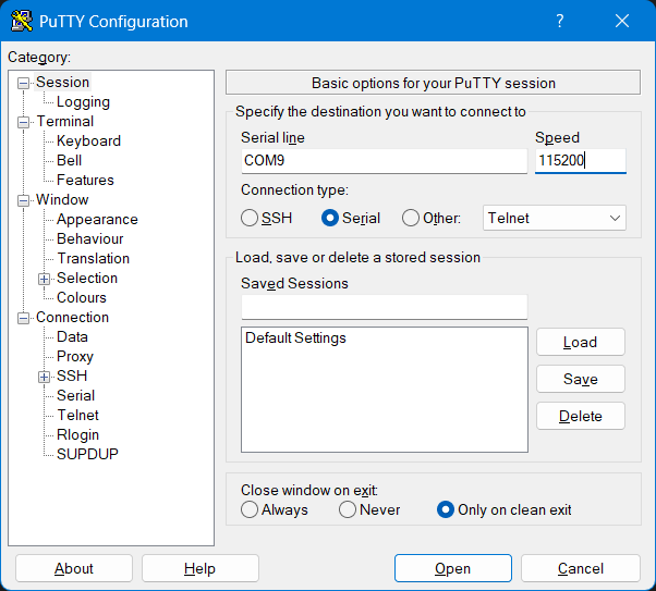
Replace the COM port with the one assigned to your TM4C123G LaunchPad. You can find it in Device Manager under Ports (COM & LPT). The baud rate must match the one set in your code (e.g., 115200).