
PWM with General-Purpose Timers
This experiment uses the General-Purpose Timer Modules (GPTM) from Experiment 7 in a new mode: PWM mode, where the timer drives a pin high and low by itself, with no interrupt and no CPU time. You will set a PWM signal's frequency and duty cycle from two registers, route the timer's output to an LED pin, and change the duty cycle at run time to fade the LED. The same technique drives servo motors, sets DC motor speed, and dims lights.
In development
This experiment is new and isn't in the lab manual yet. If something on this page doesn't match what you see on the board, tell your instructor.
Objectives
- Explain what frequency and duty cycle mean for a PWM signal, and why PWM can control brightness or speed.
- Configure a GPTM timer in PWM mode and route its output to a pin with
AFSELandPCTL. - Calculate
TAILRandTAMATCHRfor a given frequency and duty cycle. - Use the prescaler as a timer extension to reach long PWM periods, such as the 20 ms of a servo signal.
- Change the duty cycle at run time from a SysTick interrupt.
Background
What is PWM?
A pulse-width modulated (PWM) signal is a square wave whose on time is adjustable. It's described by two numbers:
- Frequency
(or period ): how often the pattern repeats. - Duty cycle
: the fraction of each period the signal is high.
If the signal switches faster than the load can follow, the load responds to the average voltage:
A 25% duty cycle on a 3.3 V pin averages about 0.83 V. An LED switched at 1 kHz flickers too fast for the eye to see, so it simply looks dimmer; a motor's inertia smooths the pulses into a lower speed. The pin itself is still purely digital: either fully on or fully off, which is why PWM wastes almost no power in the switch.
| Application | Typical frequency | What the duty cycle controls |
|---|---|---|
| LED dimming | 500 Hz to 2 kHz | Brightness |
| DC motor (through a driver) | 1 kHz to 20 kHz | Speed |
| Hobby servo | 50 Hz (20 ms period) | Angle: a 1 ms pulse is one end, 2 ms the other |
| Buzzer / tone | 100 Hz to 5 kHz | Pitch comes from the frequency; 50% duty is loudest |
Two ways to make PWM on the TM4C123
The TM4C123GH6PM has two kinds of hardware that can generate PWM:
- General-Purpose Timers (GPTM) in PWM mode: each 16/32-bit timer gives two PWM outputs (Timer A and Timer B), on the timer's CCP pins. This is what this experiment uses, because it builds directly on Experiment 7.
- Two dedicated PWM modules (M0PWM and M1PWM) with dead-band, fault inputs, and synchronized outputs, made for motor control and power converters. They are not covered here.
How GPTM PWM mode works
In PWM mode the timer runs as a 16-bit down-counter in periodic mode, exactly like Experiment 7, but instead of interrupting at zero it drives its CCP pin:
- When the counter reloads from
TAILR, the pin goes high. - The counter counts down. When it equals
TAMATCHR, the pin goes low. - The counter reaches 0, reloads, and the cycle repeats.
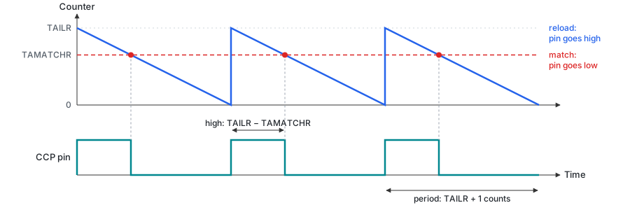
So TAILR sets the period and TAMATCHR sets where the pin turns off. The pin is high while the counter travels from TAILR down to TAMATCHR, so a smaller match value means a longer high time:
Rearranged for the values you write, with
Worked example: 1 kHz at 50 MHz with 25% duty. TAILR = 49,999. The high time is TAMATCHR = 49,999 − 12,500 = 37,499.
Keep the match inside the period
Choose TAMATCHR strictly between 0 and TAILR. A fully-on or fully-off output (0% or 100%) is an edge case for this hardware; if you need one, it's simpler to set the duty to 1% or 99%, or to switch the pin back to plain GPIO.
The prescaler is a timer extension in PWM mode
In Experiment 7 the prescaler (TAPR) divided the clock. In PWM mode it doesn't: TAPR becomes the top 8 bits of a 24-bit start value, and a second register, TAPMR, becomes the top 8 bits of the match value.
| Register | Bits it supplies | Meaning in PWM mode |
|---|---|---|
TAILR | 15:0 | Low 16 bits of the start (period) value |
TAPR | 23:16 | High 8 bits of the start (period) value |
TAMATCHR | 15:0 | Low 16 bits of the match value |
TAPMR | 23:16 | High 8 bits of the match value |
With 16 bits alone, the longest period at 50 MHz is 0x0F423F, so TAPR = 0x0F and TAILR = 0x423F.
PWM Registers
Only the registers that are new or behave differently in PWM mode are listed here; CFG, TAILR, and CTL's enable bit work as in Experiment 7.
GPTMTAMR — Timer A Mode Register Datasheet p. 729
Register: TIMERx->TAMR — GPTM Timer A Mode (Base + 0x004)
GPTMTAMR Register — Timer A Mode
Three fields select PWM mode:
| Bits | Field | Value for PWM | Meaning |
|---|---|---|---|
| 3 | TAAMS | 1 | Alternate mode: PWM |
| 2 | TACMR | 0 | Edge-count mode (required for PWM) |
| 1:0 | TAMR | 0x2 | Periodic |
Together: TIMERx->TAMR = 0x0A. For Timer B, the same fields are in TBMR (TIMERx->TBMR = 0x0A).
GPTMTAMATCHR — Timer A Match Register Datasheet p. 758
Register: TIMERx->TAMATCHR — GPTM Timer A Match (Base + 0x030)
GPTMTAMATCHR Register — Timer A Match
The low 16 bits of the value at which the output goes low; PWM mode always runs the timer as a 16-bit half, so bits 31:16 play no part. Timer B uses TBMATCHR (Base + 0x034).
GPTMTAPR and GPTMTAPMR — Prescaler and Prescale Match Datasheet p. 760
Registers: TIMERx->TAPR (Base + 0x038) and TIMERx->TAPMR (Base + 0x040)
GPTMTAPR Register — Timer A Prescale (in PWM mode: start value bits 23:16)
GPTMTAPMR Register — Timer A Prescale Match (in PWM mode: match value bits 23:16)
In PWM mode, bits 7:0 of these registers extend the start value and the match value to 24 bits, as described above. Write 0 to both when the period fits in 16 bits. Timer B uses TBPR and TBPMR.
GPTMCTL — Output Level Datasheet p. 737
Register: TIMERx->CTL — GPTM Control (Base + 0x00C)
GPTMCTL Register — Timer Control
Besides TAEN (bit 0), PWM mode uses:
- Bit 6 (TAPWML): PWM output level. 0 = as described above (high, then low at the match); 1 = inverted (low, then high at the match).
- Bit 14 (TBPWML): the same for Timer B.
The examples leave TAPWML at 0.
Routing the Timer to a Pin
A pin can be plain GPIO (driven by DATA) or connected to one of several peripherals. Two GPIO registers select which:
GPIOAFSEL — Alternate Function Select Datasheet p. 671
Register: GPIOx->AFSEL (Base + 0x420)
GPIOAFSEL Register (Port x) — Alternate Function Select
Setting bit n hands pin n to a peripheral. Writing DATA no longer changes the pin.
GPIOPCTL — Port Control Datasheet p. 688
Register: GPIOx->PCTL (Base + 0x52C)
GPIOPCTL Register (Port x) — Port Control
PMCn selects the peripheral for pin n.
Each pin has a 4-bit field (pin n uses bits
GPIOF->PCTL = (GPIOF->PCTL & ~0x00000F00) | 0x00000700; // PF2's field (bits 11:8) = 7DEN must still be set, as for any digital pin. DIR doesn't matter: the peripheral controls the direction.
Which timer drives each LaunchPad LED
The three LEDs happen to sit on timer CCP pins, so every LED can be dimmed in hardware:
| Pin | LED | Timer output | PCTL field | Timer half |
|---|---|---|---|---|
| PF1 | Red | T0CCP1 | bits 7:4 = 7 | Timer0 B |
| PF2 | Blue | T1CCP0 | bits 11:8 = 7 | Timer1 A |
| PF3 | Green | T1CCP1 | bits 15:12 = 7 | Timer1 B |
CCP0 is always Timer A and CCP1 Timer B. Because PWM mode needs the timer split into 16-bit halves (CFG = 0x4), Timer1 can drive the blue and green LEDs at the same time, each with its own duty cycle.
Configuration Steps
To output PWM on a pin with Timer x, half A:
- Enable the clocks:
SYSCTL->RCGCGPIOfor the port andSYSCTL->RCGCTIMERfor the timer, then wait a few cycles. - Hand the pin to the timer: set its bit in
GPIOx->AFSEL, write 7 into itsGPIOx->PCTLfield, and set its bit inGPIOx->DEN. - Disable the timer half: clear
TAENinTIMERx->CTL. - Select 16-bit mode:
TIMERx->CFG = 0x4. - Select PWM, periodic:
TIMERx->TAMR = 0x0A. - Write the period:
TIMERx->TAILR(andTIMERx->TAPRfor periods above 16 bits). - Write the match:
TIMERx->TAMATCHR(andTIMERx->TAPMR). - Enable the timer half: set
TAENinTIMERx->CTL.
To change the duty cycle later, write a new value to TAMATCHR; there's no need to stop the timer.
| Register | Purpose | Value in Example 1 |
|---|---|---|
GPIOF->AFSEL | Hand PF2 to a peripheral | bit 2 set |
GPIOF->PCTL | Choose T1CCP0 for PF2 | bits 11:8 = 7 |
TIMER1->CFG | 16-bit mode | 0x4 |
TIMER1->TAMR | PWM, periodic | 0x0A |
TIMER1->TAILR | Period | 49,999 (1 kHz) |
TIMER1->TAMATCHR | Where the pin goes low | 37,499 (25%) |
TIMER1->CTL | Start | TAEN = 1 |
GPTM PWM Configuration Summary
Examples
Setting up the project
This experiment runs on the TM4C123 LaunchPad. If you haven't made a project yet, follow the Tiva LaunchPad Project guide first, and make sure its blinking-LED test works.
Target device: TM4C123GH6PM
Both examples assume the 50 MHz system clock set by SystemInit, as in Experiment 7.
Example 1: Dimming an LED
This example sets up Timer1A in PWM mode at 1 kHz with a 25% duty cycle on PF2, so the blue LED glows at a quarter of its brightness. Try changing DUTY to 5, 50, and 95 and re-flashing.
#include "TM4C123.h"

#define BLUE_LED  (1 << 2)              // PF2 = T1CCP0 (Timer1A's PWM pin)
#define PERIOD    50000                 // 1 kHz at 50 MHz: 50,000,000 / 1,000
#define DUTY      25                    // Percent of each period the LED is on


int main(void)
{
	SYSCTL->RCGCGPIO  |= (1 << 5);		// Enable clock to GPIOF
	SYSCTL->RCGCTIMER |= (1 << 1);		// Enable clock to Timer1

	__asm__("NOP");						// Wait for clock stabilization
	__asm__("NOP");
	__asm__("NOP");

	// PF2 is driven by Timer1A, not by GPIOF->DATA
	GPIOF->AFSEL |= BLUE_LED;						// Alternate function on PF2
	GPIOF->PCTL   = (GPIOF->PCTL & ~0x00000F00)		// PF2's field is bits 11:8
	              | 0x00000700;						// 7 = T1CCP0
	GPIOF->DEN   |= BLUE_LED;						// PF2 is a digital pin

	TIMER1->CTL      &= ~(1 << 0);		// Disable Timer1A while configuring
	TIMER1->CFG       = 0x4;			// 16-bit mode (PWM uses a split timer)
	TIMER1->TAMR      = 0x0A;			// TAAMS = 1 (PWM), TACMR = 0, TAMR = 2 (periodic)
	TIMER1->TAPR      = 0;				// No extension: the period fits in 16 bits
	TIMER1->TAILR     = PERIOD - 1;		// Period: TAILR + 1 counts
	TIMER1->TAMATCHR  = (PERIOD - 1) - (PERIOD / 100) * DUTY;	// Pin goes low here
	TIMER1->CTL      |= (1 << 0);		// Enable Timer1A: the pin starts toggling

	while (1)							// The timer drives the pin by itself:
	{									// the CPU has nothing left to do
	}
}
Explanation:
GPIOF->AFSELandGPIOF->PCTLdisconnect PF2 fromGPIOF->DATAand connect it to T1CCP0, Timer1A's output.TIMER1->CFG = 0x4splits Timer1 into two 16-bit halves; PWM mode only works on a half.TIMER1->TAMR = 0x0AsetsTAAMS = 1(PWM),TACMR = 0, andTAMR = 2(periodic).TIMER1->TAILR = 49,999givescounts per period: 1 ms, or 1 kHz. TIMER1->TAMATCHR = 37,499: the pin is high forcounts, 25% of the period. - The
while (1)loop is empty and no interrupt is used: the timer generates the signal on its own.
See it on the oscilloscope
Probe PF2 on the LaunchPad header (ground on any GND pin). You should see a 1 kHz square wave that is high for 250 µs of every 1 ms. Changing DUTY changes the width of the high part, not the frequency.
Example 2: Fading an LED with SysTick
This example keeps the PWM setup from Example 1 and adds a SysTick interrupt every 10 ms. Each interrupt moves the duty cycle one percent up or down, so the blue LED "breathes": it fades in over about a second, then out again.
#include "TM4C123.h"

#define BLUE_LED  (1 << 2)              // PF2 = T1CCP0 (Timer1A's PWM pin)
#define PERIOD    50000                 // 1 kHz at 50 MHz

volatile uint32_t level = 1;			// Brightness in percent, 1 to 99
volatile int      step  = 1;			// +1 while getting brighter, -1 while dimming


// Keep the match strictly between 0 and TAILR: the two ends are special cases
void pwm_set(uint32_t percent)
{
	if (percent < 1)  percent = 1;
	if (percent > 99) percent = 99;
	TIMER1->TAMATCHR = (PERIOD - 1) - (PERIOD / 100) * percent;
}


int main(void)
{
	SYSCTL->RCGCGPIO  |= (1 << 5);		// Enable clock to GPIOF
	SYSCTL->RCGCTIMER |= (1 << 1);		// Enable clock to Timer1

	__asm__("NOP");						// Wait for clock stabilization
	__asm__("NOP");
	__asm__("NOP");

	GPIOF->AFSEL |= BLUE_LED;						// PF2 driven by Timer1A
	GPIOF->PCTL   = (GPIOF->PCTL & ~0x00000F00) | 0x00000700;	// 7 = T1CCP0
	GPIOF->DEN   |= BLUE_LED;

	TIMER1->CTL   &= ~(1 << 0);			// Disable Timer1A while configuring
	TIMER1->CFG    = 0x4;				// 16-bit mode
	TIMER1->TAMR   = 0x0A;				// PWM, periodic
	TIMER1->TAPR   = 0;
	TIMER1->TAILR  = PERIOD - 1;
	pwm_set(level);						// Start almost off
	TIMER1->CTL   |= (1 << 0);			// Enable Timer1A

	SysTick_Config(SystemCoreClock / 100);	// SysTick interrupt every 10 ms

	while (1)
	{
	}
}


// Every 10 ms: one step brighter or dimmer. 99 steps each way = about 2 s per breath.
void SysTick_Handler(void)
{
	level += step;
	if (level >= 99) step = -1;
	if (level <= 1)  step = +1;
	pwm_set(level);
}
Explanation:
pwm_set()converts a percentage into a match value and clamps it to 1–99%, keeping the match strictly inside the period.SysTick_Config(SystemCoreClock / 100)gives a 10 ms tick, as in Experiment 7.SysTick_Handler()only writes a newTAMATCHR. The timer keeps running; the new duty cycle takes effect from the next period.- Two timers work together: Timer1A makes the fast 1 kHz signal, and SysTick changes it slowly.
Why does the fade look uneven?
The eye's response to brightness isn't linear: the change from 1% to 10% looks much bigger than from 60% to 70%. Real dimmers correct for this with a lookup table (a "gamma curve"). You can try it in the lab work.
Lab work
Lab work 1: RGB Color Mixing
Drive all three LEDs with PWM to mix colors: Timer0B on PF1 (red), Timer1A on PF2 (blue), and Timer1B on PF3 (green), all at 1 kHz.
Requirements:
- Configure the three outputs using the table in Which timer drives each LaunchPad LED. Timer B uses
TBMR,TBILR,TBMATCHR, andTBEN(bit 8 ofCTL). - Write a function
set_color(uint32_t r, uint32_t g, uint32_t b)that takes three percentages. - In the main loop, cycle through at least four colors (for example orange, purple, cyan, and white), holding each for one second. Use SysTick for the delay.
Hint: Timer0 and Timer1 each need their own RCGCTIMER bit, and Timer1's two halves share one CFG and one CTL register: configure both halves before enabling either.
Lab work 2: Button-Controlled Brightness
Use the two LaunchPad buttons to set the blue LED's brightness: SW1 (PF4) makes it brighter by 10%, SW2 (PF0) makes it dimmer by 10%, limited to 10–90%.
Requirements:
- Use interrupt-driven input for both buttons, as in Experiment 6. Remember that PF0 is locked and must be unlocked with
GPIOF->LOCKandGPIOF->CRfirst. - Debounce both buttons with a millisecond counter from SysTick, as in Experiment 7, Lab work 1.
- Add the current brightness to the Watch window and check it changes in steps of 10.
Extra: Replace the linear steps with a 10-entry lookup table that looks evenly spaced to the eye (for example 1, 2, 4, 7, 11, 18, 28, 43, 66, 99) and compare.
Lab work 3: Color Knob with the ADC
Turn a potentiometer to pick the RGB LED's color: as the knob goes from one end to the other, the LED should move smoothly from red to green to blue and back toward red.
Requirements:
- Reuse the three PWM outputs and
set_color()from Lab work 1. - Read the potentiometer on AIN0 (PE3) with sample sequencer 3, by polling, as in Experiment 9, Example 1. Take a new reading every 20 ms, timed with SysTick.
- Map the 12-bit reading (0 to 4095) to a color as described in the hint, and update the LED after every reading.
- Add the ADC reading and the three percentages to the Watch window, and check they change as you turn the knob.
Wiring: the potentiometer's two outer pins to 3.3 V and GND, and its middle pin (the wiper) to PE3, as in Experiment 9.
Hint: mapping the knob to a color
Split the knob's range into three equal parts. In each part, one color fades out while the next fades in:
| Reading | Red | Green | Blue |
|---|---|---|---|
| 0 to 1365 | 99% to 0% | 0% to 99% | 0% |
| 1366 to 2730 | 0% | 99% to 0% | 0% to 99% |
| 2731 to 4095 | 0% to 99% | 0% | 99% to 0% |
With v as the reading, part = (v * 3) / 4096 gives which third you're in (0, 1 or 2), and f = ((v * 3) % 4096) * 99 / 4096 how far through it you are (0 to 98). In part 0, red is 99 - f and green is f; parts 1 and 2 follow the same pattern. Let set_color() clamp anything below 1% to 1%, as pwm_set() does.